Notebook 11 - Prepare for revit pipeline
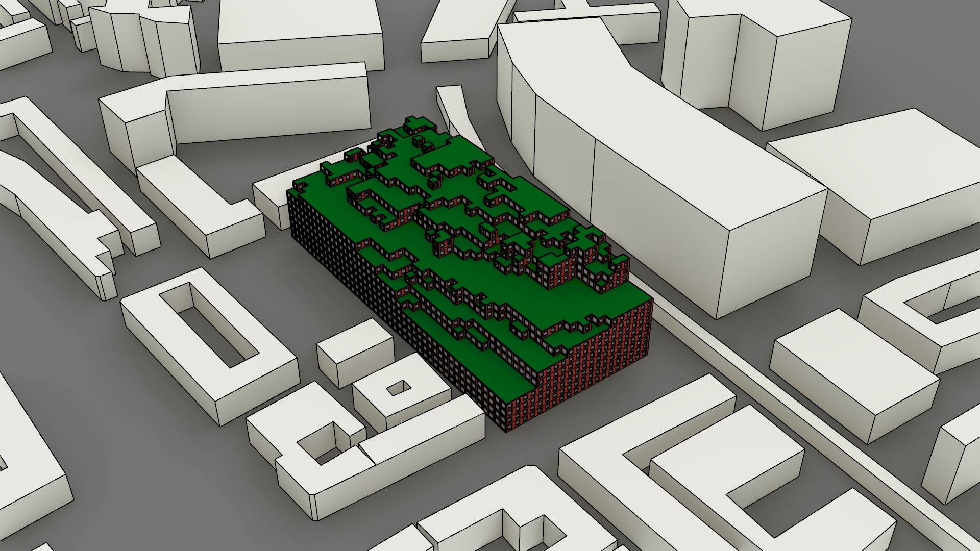
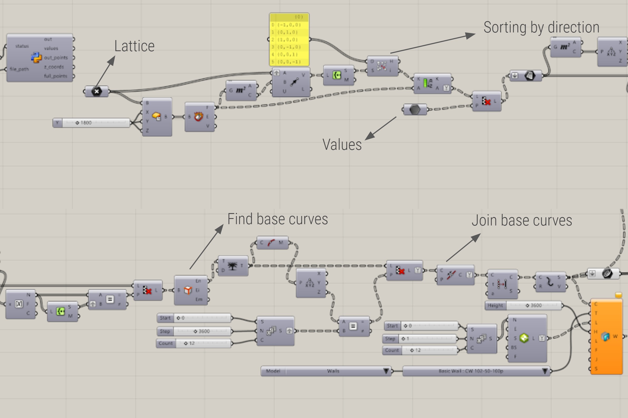
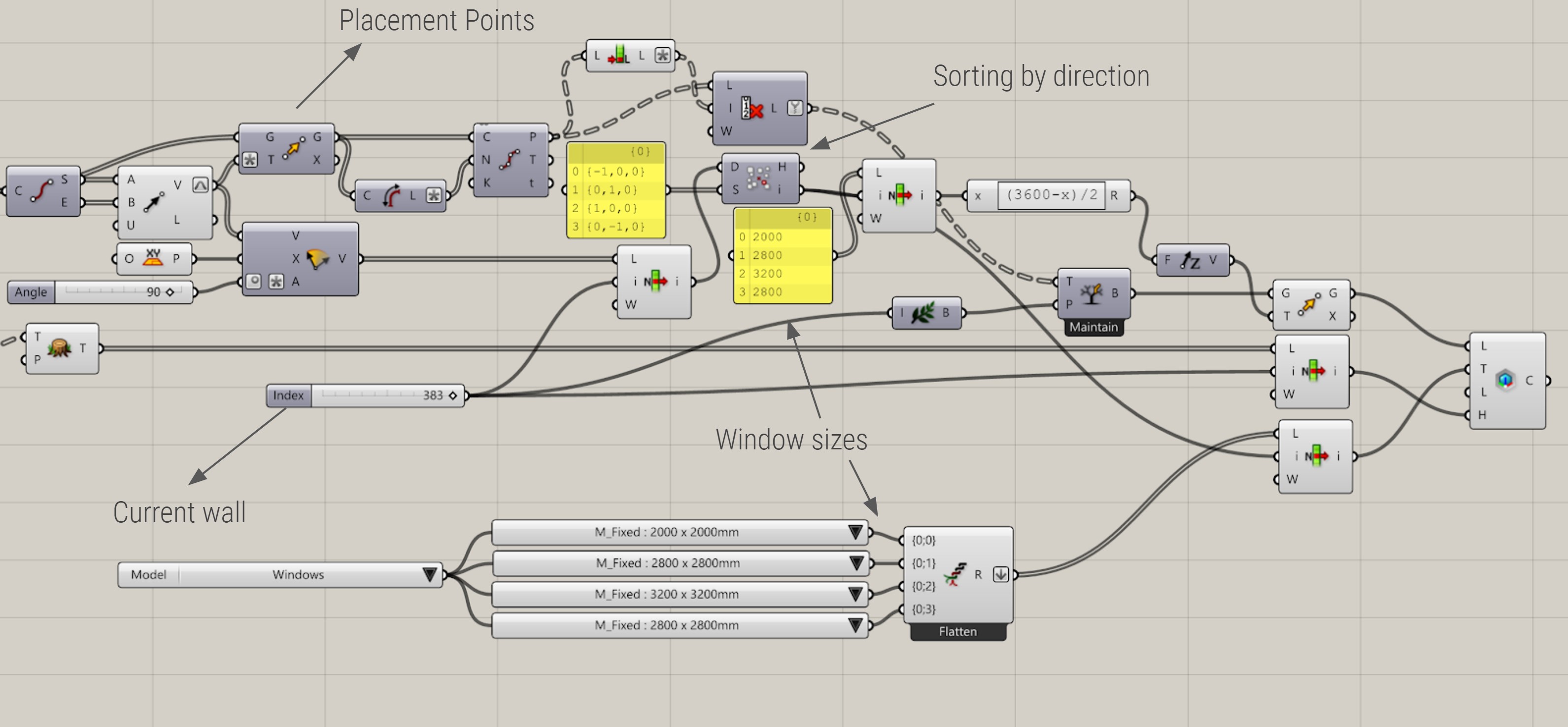
This grasshopper script for Rhino.Inside Revit translates the lattice points to an actual building with walls, floors and windows. First, the boundary curves of each floor are established using the previously established facades list. Rhino.Inside will only place walls on straight base curves so the curves are split into segments and the walls are placed. Secondly, the floors are generated. In this project, we wanted to create a green roof. This meant that the floor type for inner floors had to be different from the floor type on the outside. This was done with the floors/roof list from the previous script. Using a region difference the boundary curves of the two roofs were found and the floors were placed. The most tedious part of this workflow was the placement of the windows. We wanted to place one window per voxel facade and have different window types based on the directions they would face. Establishing a list of points that was synchronous with window type for each wall was not too difficult. The window component in Grasshopper did however not behave in an expected manner. Instead of checking the first list against the first wall in a grafted input, it would check every wall against all lists and crash on the computational impossibility of this task. This behavior is probably due to the very recent release of Rhino.Inside. After having tried every way of inputting the data I accepted this reality and split the data into one list and one wall at a time. While this worked it did mean that I had to bake individual lists of windows for 383 walls, which was honestly painfully tedious. In the end, I would still say it was worth it due to the easy workflow of Revit to Twinmotion which was used to make the renders without any material, or UV mapping issues which are so common when exporting directly from Rhino.
Additional diagrams
The Following Figure 64 represents the grasshopper script used in this step shows the generation of floors.
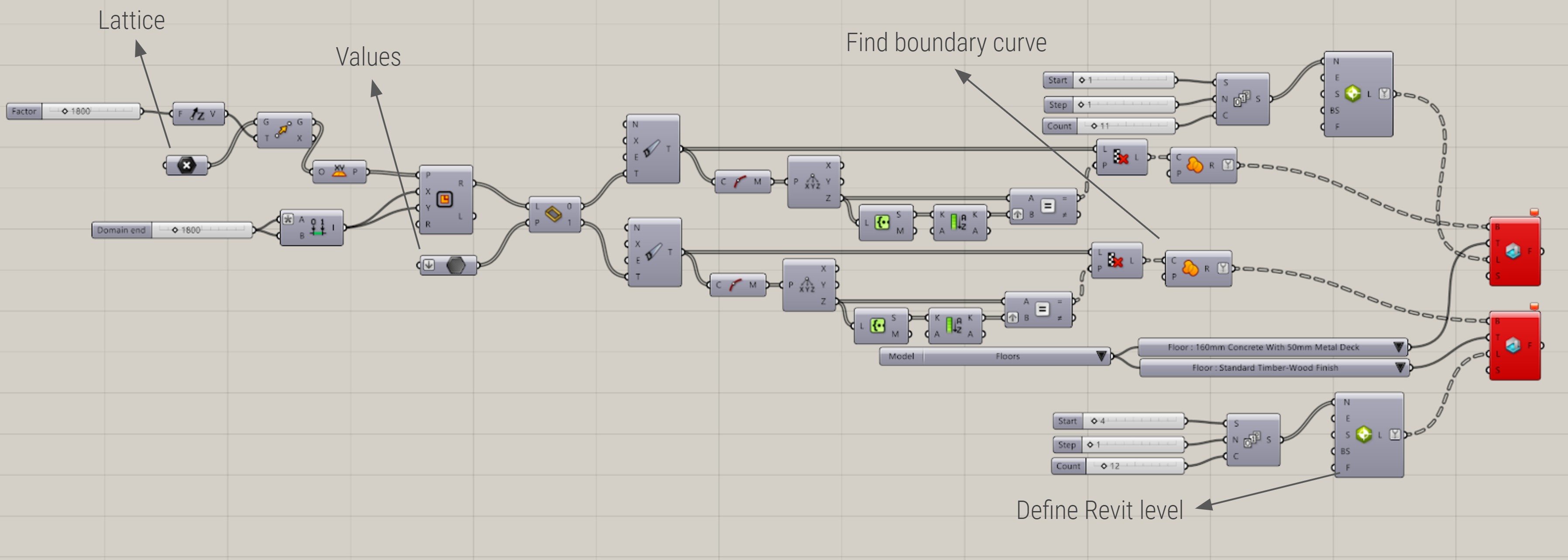
Figure X shows the steps leading to the generation of walls.
In Figure X the tedious process of generating the windows is visible.
A visualisation of the walls and floors generated in revit, is visible in Figure X
Pseudo code
For a better understanding of the code, we wrote a pseudo code. The notebook, and the other notebooks, can be found here.
#load the complete lattice

#Create a coordinates list
for each voxel in complete lattice
    establish coordintes as [x, y, z]

#Find neighbouring voxels
facade list = []
floor/roof list = []
#Data structure = [x, y, z, [North, East, South, West](facades), [Top, Bottom](roof/floor)]
for each coordinate
    for direction x,y (-1, +1)
        check if [x, y, z] are not in coordinates
        if True
            #facade here
            append a one to the appropriate index in facade list
    for direction z (-1, +1)
        check if [x, y, z] are not in coordinates
        if True
            #floor/roof here
            append a one to the appropriate index in roof/floor list
    Establish result list as [x, y, z, [facades], [roof/floor]]

#Export data
Export result list as 'facade_3_6.txt'
Visualisations of the result
GIF
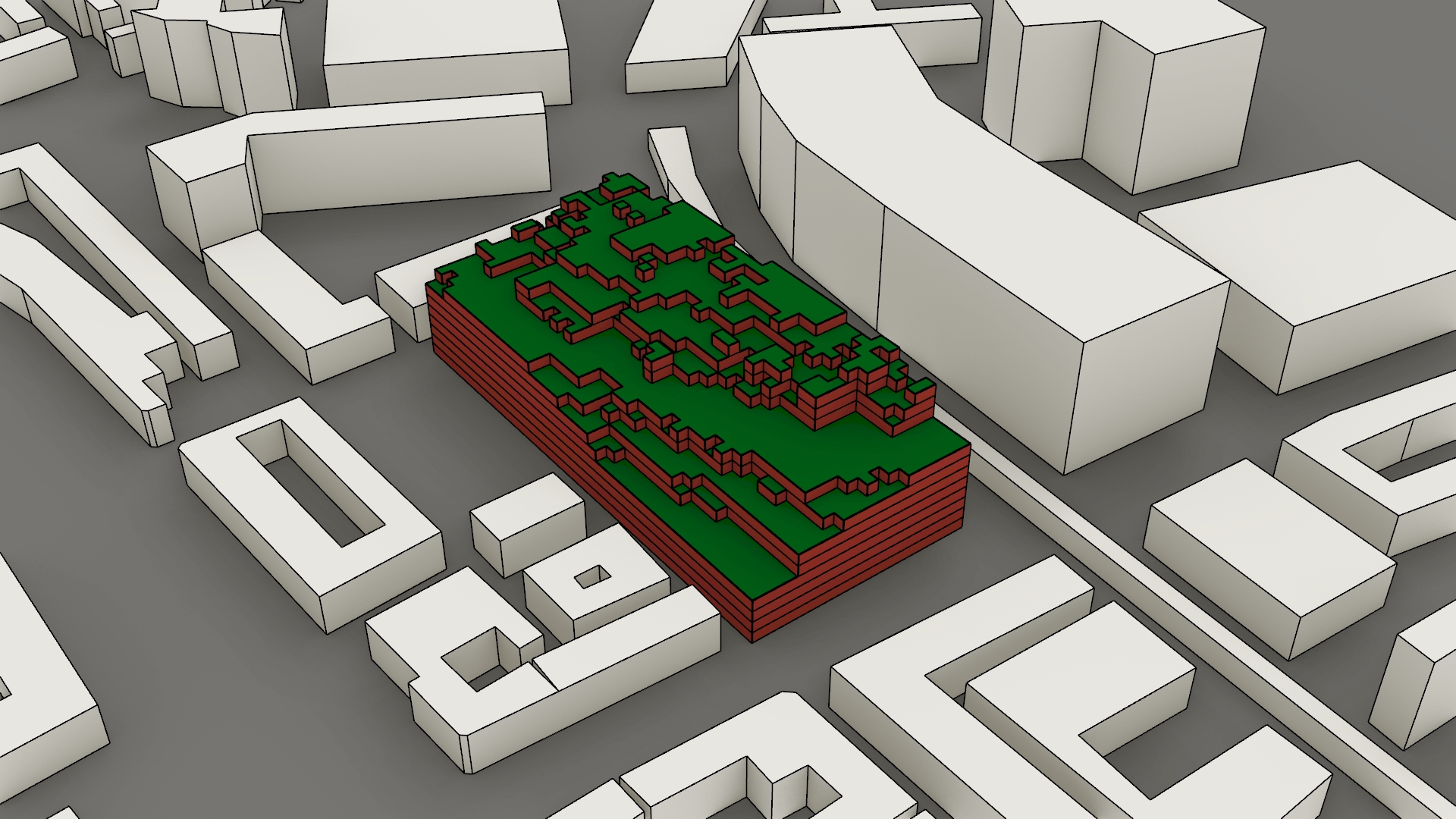
Voxelcloud
In Figure 69, the windows have been added to the revit model, this is the end result