Notebook 12 - Generative Relations corridors
In this notebook the corridors and shafts have been created for the building. To showcase this process the flowchart will be presented, whereby additional diagrams have simplified every step, in comparison to the pseudo codes that zooms in on the definitive script. Moreover the visualisations of the end product will be revealed and lastly the reflection will be discussed.
Flowchart
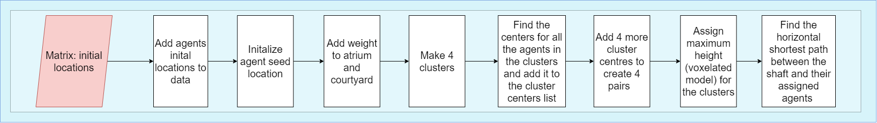
In Figure 70 the flowchart for the making of the shafts and corridors is shown. In which, the global steps that have been executed are presented.
Additional diagrams
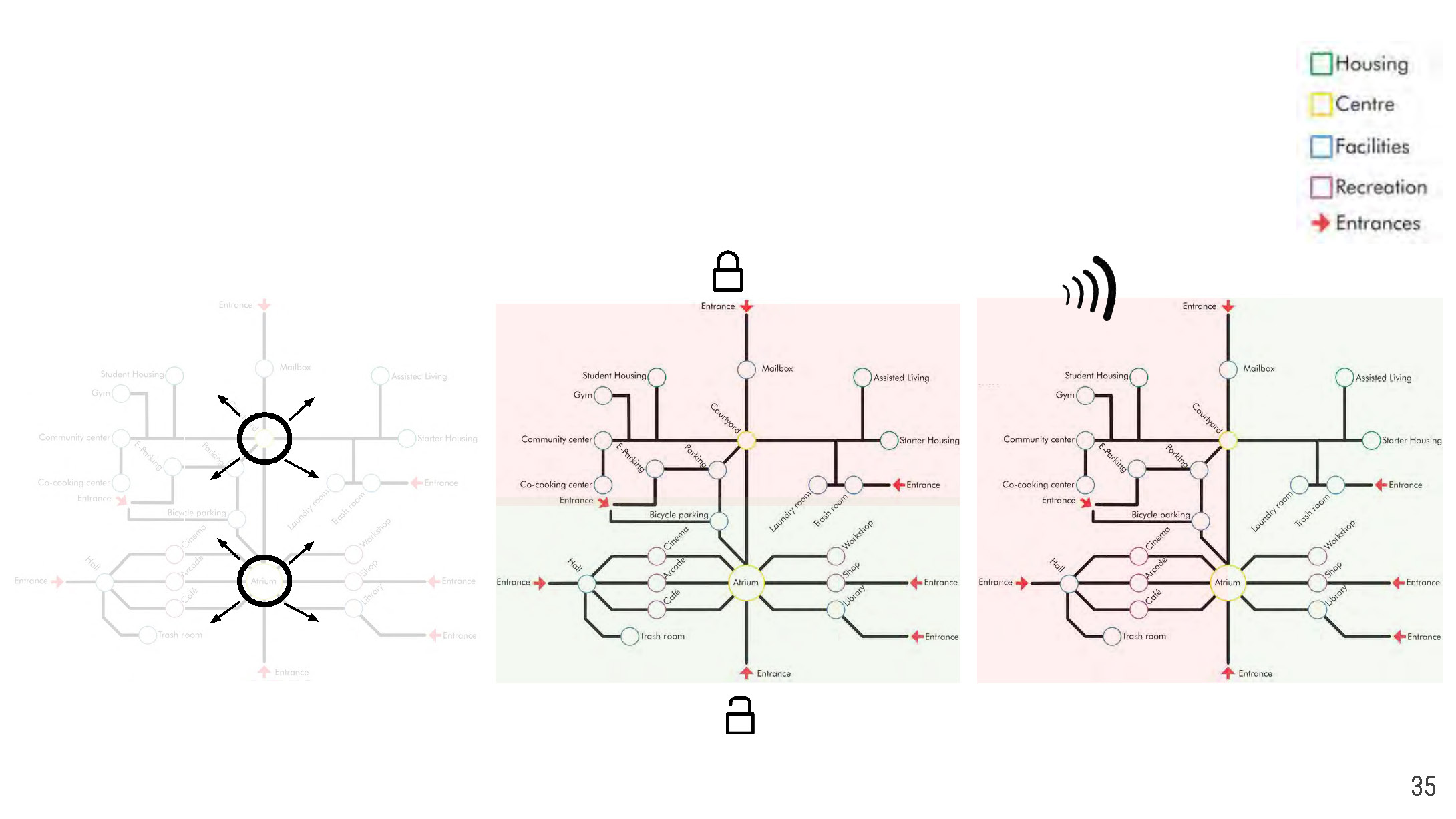
Our traffic space is based on our metro network. The shafts have been put in the center of the building, which is the atrium and the courtyard. In this way, public and private will be separated from each other, as you can see in Figure 71. Subsequently, there are 2 shafts for each center, so that the quiet and noisy facilities can also be separated from each other.
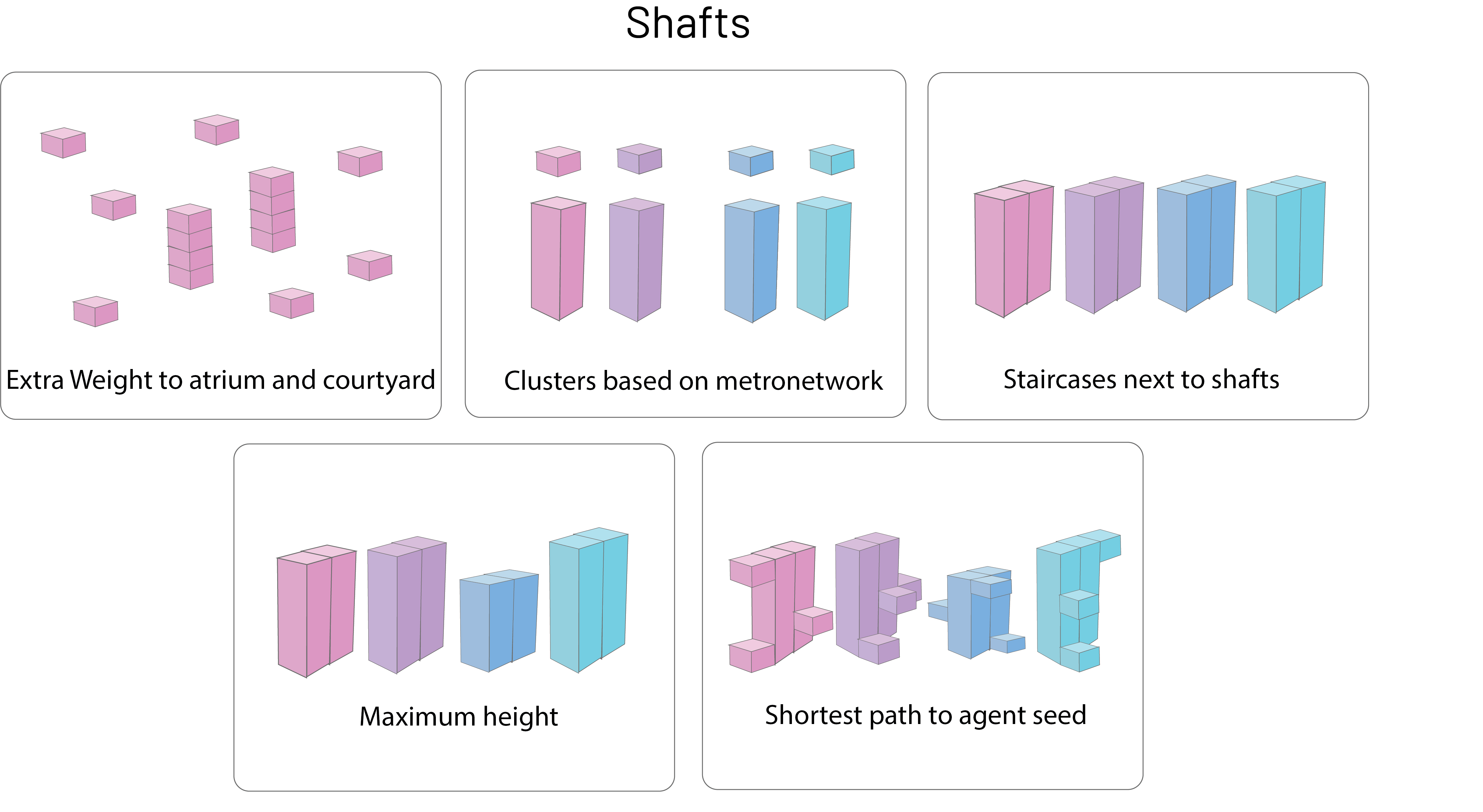
In the next diagrams (Figure 72), the main steps of the process have been visualized. Extra weight has been added to the atrium and courtyard. This way the attraction of the shafts to the atrium and courtyard gets stronger. As a result, the shafts are located close to the atrium and courtyard. The clusters are based on the metro network that has been discussed in previous Figure X. Furthermore, an extra column is placed next to every shaft, which stands for a staircase, and we assigned the shafts to have a maximum height to fit our voxelated model. In conclusion, the corridors take the shortest path to grow towards their agent seeds that belong to their cluster.
Pseudo code
For a better understanding of the code, we wrote a pseudo code. The notebook, and the other notebooks, can be found here.
#load the complete lattice

#Create a coordinates list
for each voxel in complete lattice
    establish coordintes as [x, y, z]

#Find neighbouring voxels
facade list = []
floor/roof list = []
#Data structure = [x, y, z, [North, East, South, West](facades), [Top, Bottom](roof/floor)]
for each coordinate
    for direction x,y (-1, +1)
        check if [x, y, z] are not in coordinates
        if True
            #facade here
            append a one to the appropriate index in facade list
    for direction z (-1, +1)
        check if [x, y, z] are not in coordinates
        if True
            #floor/roof here
            append a one to the appropriate index in roof/floor list
    Establish result list as [x, y, z, [facades], [roof/floor]]

#Export data
Export result list as 'facade_3_6.txt'
Visualisations of the result
Growing video
The gif gif's a quick snapshot of the voxel seeds, shafts and corridors.
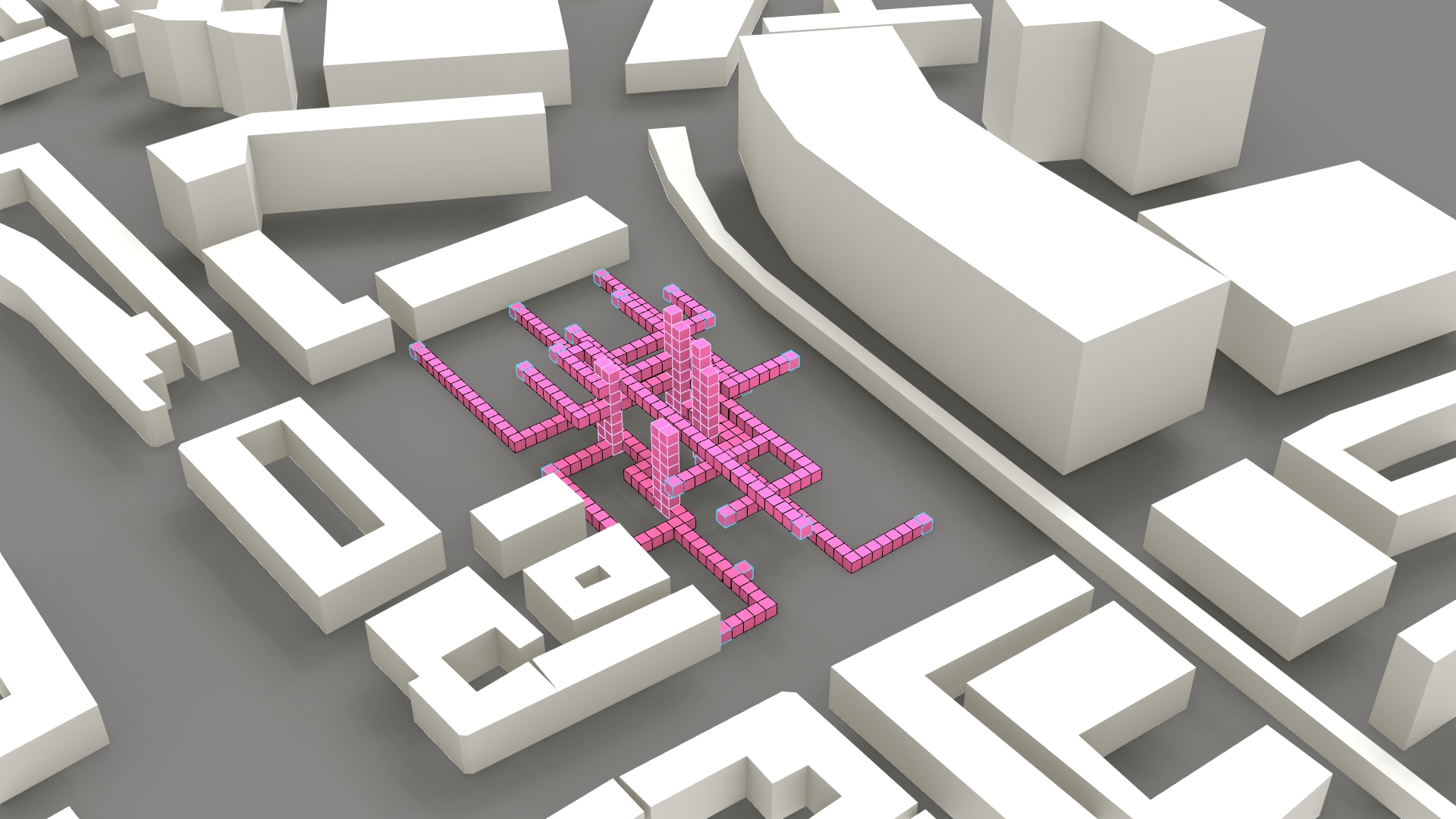
Voxelcloud
Subsequently in Figure 74 you can see the end result of the circulation space.
Reflection
For the growing of the corridors and the shafts, the agent seeds have been located. The shafts have a strong preference for where they would like to be positioned close to and the shafts take the shortest route to grow to their agents' seeds. All in all a functioning system that creates indispensable corridors. Nevertheless, an important footnote is that the corridors only grow towards the agents' seeds, which means that some functions that are placed on multiple floors do not have a corridor. Criteria that would have been incorporated if there was more time during this course.